Aquarium Heater Controller - Timer Method
Poor Signal Integrity
The problem with using hysteresis was signal noise. The unshielded leads of the temperature sensor ran next to a lot of noisy contraptions:
- Aquarium Air Pump
- Aquarium Filter
- Wireless Router
- Cable Modem
- Timing Motor Based Light Switch
- Wireless Headphone Transmitter
- Wireless Mouse
- Wireless Keyboard
- Cell Phone
- Cordless Phone
- Florescent Light
- Poorly Built Breadboard Circuit
That millivolt-range signal didn't even stand a chance.
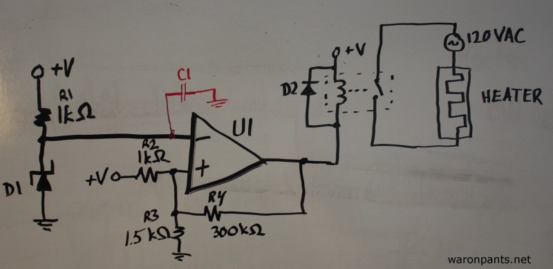
With my multimeter set to AC, the temperature sensor leads at the breadboard measured about 5VACRMS on top of the ~2.978VDC. This meant that the heat would never turn off. This led me to add a bypass capacitor to the sensor input, called C1 in the schematic from when I tried the hysteresis method.

When the temperature sensor (D1) outputs a voltage less than the voltage output by the potentiometer (R2), the output of the
I tried twisting the leads together, but that didn't go much. The lowest I could bring the noise to with the capacitors I had on hand was 50mVACRMS. Two orders of magnitude is great. After all, that's -20dB, but it's still more than the hysteresis threshold I was counting on. It was time for plan B.
What Am I Really Trying to Accomplish?
Once the aquarium temperature hits the low threshold, warm the water. What if I just adjust the trigger to activate at the low threshold, turn the heater on for an hour or so, then wait for another trigger? That could work... and any electronics lab worth its salt has an extra 555 laying around. I'll give it a shot.
The Updated Design

When the output voltage of the temperature sensor (D1) is less than the threshold voltage set by the potentiometer (R2), the output of the op-amp/comparator (U1) will be low. A high-to-low transition ("negative edge") on the trigger pin (pin 2) of the 555 timer (U2) will set the output (pin 3) high for the period determined by R3 and C2. The relay switch is closed while the timer's output is high, turning on the heater.
The period of the timer is determined by this formula:

I used a 1.5MΩ resistor and a 2200μF capacitor for a period of approximately 1 hour.
Good Enough
This design worked well for me. It turned the heater on for an hour when the aquarium was cold. It worked well enough until I came back from vacation. There was one problem, though. Sometimes when the relay was supposed to switch off, it would switch on and off like a buzzer for a minute. This is bad for the relay, and worse, for the heater. Because this was temporary and I planned on buying a functioning heater after vacation, I called this design done.
A week later, I was able to replace all this with a proper heater.
