Automatic Door Light
I like to automate things, as seen in my fish feeder project. I have parts everywhere, and I wanted to build something. The closet that I keep all of my parts had no light. If I was going to add a light, I may as well make it automatic. Toggle switches are for people who don't have too much time on their hands!
First, I decided what I really want to get out of this project.
- No bulky power supply
- Doesn't draw much energy when off (Toggle switches are a better alternative to a high electric bill.)
- Buy as few parts as possible
- No AC in the door sensor switch (Although I technically can, it just seems like a bad idea.)
- No microcontrollers (No need for the overhead)
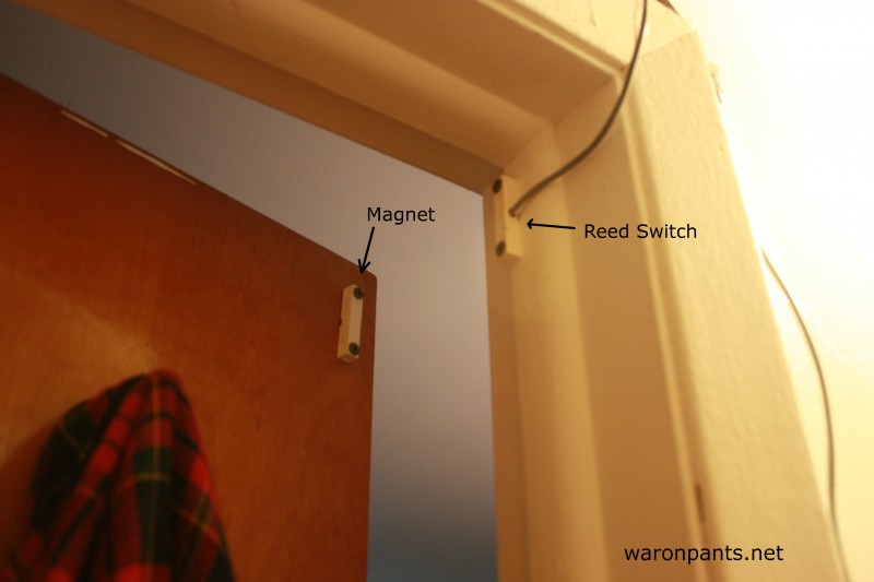
I have a bunch of reed switches sitting around. The magnet is mounted on the door. The switch is on the door frame. The contacts of the switch are closed when the door is closed.
Idea 1
My first idea was to create as much of an all-AC circuit as possible.
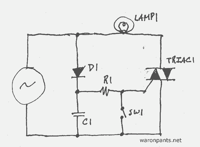
This design uses a triac as the light switching mechanism. The AC source is 120 VAC. The theory is this:
- D1 and C1 create a half-wave DC source of approximately 165V.
- R1 lowers the voltage and current to the turn-on threshold voltage and current of TRIAC1 (typically around 2V @ 20 mA).
- SW1 is the reed switch. While the door is shut, the gate of TRIAC1 is shorted to ground, shutting LAMP1 off.
If I hadn't used a CFL, I could insert a potentiometer to make the light dimmable. This design fails my needs for two reasons.
Problem 1
The triac must have a heat sink. This increases the bulk of the circuit. I also don't want the circuit to generate much heat. It will be in a closet, and I don't want even the slightest chance of starting a fire.
Problem 2
The circuit would waste a lot of energy as heat.
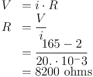
I would need a 8k2 Ω resistor at what power rating?
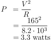
I would need a 5W 8k2Ω resistor just to radiate heat when the light is off. I knew I could do better.
Idea 2
The second idea was to use a relay, which meant I needed to regulate the DC voltage. If I go over the threshold of a triac gate a little, the gate will stay saturated without a problem; if I go over the turn-on voltage of a relay too much, the relay dies. I tried to minimize my part count and included a Zener diode.

As it turned out, RELAY1 required 5V @ 10mA. Because D2 could handle up to 20mA, R2 wasn't needed at all. R3 was a high value pull-down resistor for Q1. D3 was included to suppress inductive surges from RELAY1. R1 lowered the line voltage from 165V to 5V @ ~12mA. 10mA for RELAY1 plus 2mA just-in-case extra current for D2, R3, and Q1.
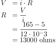
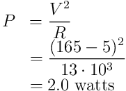
For safety, a 2.5W or higher 13kΩ resistor would be needed. That still seemed like a lot of "off" power. Plus, I didn't have a P-FET laying around.
Idea 3
The third idea was more of an intermediary step between ideas two and four. The previous two designs caused me to add more requirements:
- Due to the relay, I need 5VDC. It doesn't need to be clean, but it must be steady.
- To minimize power consumption, the current draw shouldn't be fixed.
I would have been able to activate the relay through SW1, but I actually needed the opposite. I needed to invert the signal, creating SW1.

Just looking at this circuit, it's apparent that this it entire too complicated to merely turn a light on. R1, R2, D2, and Q1 combine to become a crude voltage regulator. When the door is closed, SW1 is closed. This turns on Q2, turning off Q3 and disabling RELAY1. When the door is open, SW1 is open. This turns off Q2, turning on Q3 and enabling RELAY1.
I was on the right track. Now, I just needed to refine the circuit. For one thing, rather than inverting SW1, why not make pull to ground in the first place?
Idea 4
I started reading about transformer-less power supplies. While I was "window shopping" a few electronics sites, I found a component that has since changed all my digital electronics designs: a miniature switching power supply.
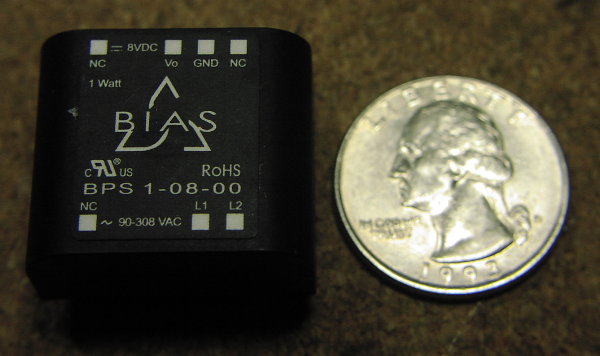
(Image source)
Although a 5V version exists, wherever I found it only had an 8V output, so I picked up 5V 150mA regulator with it for a couple cents.

PS1 is the miniature power supply. U1 is the 5V regulator. R1 is a high-value pull-up resistor. I arbitrarily chose 1MΩ. I probably could have gone higher, but it's what I had on hand.
I decided that I was going to use this design. The efficiency of PS1 is 70%. The efficiency of U1 has to be determined. According to the data sheet, my LM75L05 has a quiescent current of ~3mA with an input voltage of 8V. It's output impedance is <1Ω, which is insignificant to this design.

U1 has an efficiency of 80%.
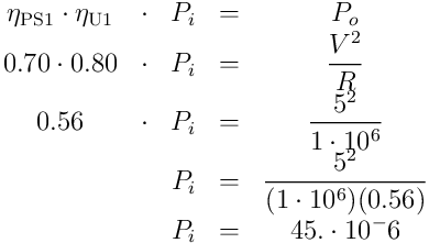
The "off" power is 45 μW. That's better than I expected.
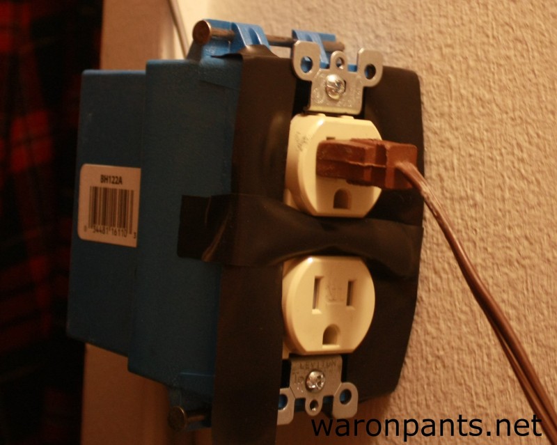
I soldered everything together. By deadbugging and wrapping everything in layers of electrical tape, I was able make the device very compact. Rather than leaving everything exposed, I bought an electrical socket and junction box from Home Depot. The device fit inside the box with room to spare. I didn't get a face plate so the box would be a flush as possible to the wall. I can't actually mount it inside the wall; I rent my apartment.
I plugged the device into the receptacle outside of the closet and screwed in the reed switch. I mounted the light socket and plugged it in. It works perfectly.

