Determining Inductance
I had wound my own toroid for a boost converter than I am building. The problem I always had was measuring the inductance of the inductor. I recently acquired some old lab equipment. (Thanks, Jim!) Now, it is extremely easy to find the inductance. Using only a signal generator and a voltmeter, I can find the inductance using a simple voltage divider circuit.

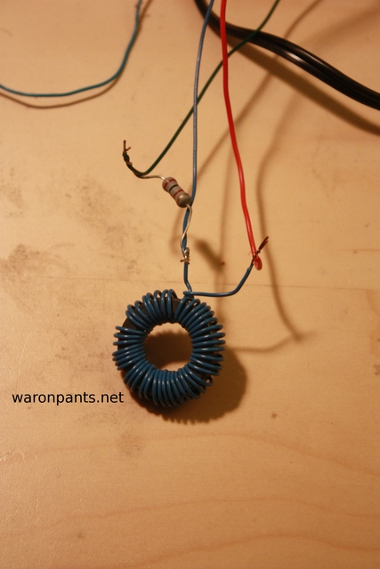
First, I connected the circuit as shown. I didn't use a breadboard. If the frequency required was high enough, the capacitance of the breadboard would have thrown off my measurements. If you've ever tried to build an RF circuit or efficient boost/buck converter before, you've probably experienced this.

Then, I shorted out the inductor with a jumper wire to find the loaded output voltage of the signal generator. After removing the jumper wire, I adjusted the frequency of the sine wave until the voltmeter read half of the original reading. This means that an equal voltage is dropped across both the inductor and resistor. Being in series, the same amount of amperage is flowing through both as well. Therefore, their impedance values were both equal at that frequency.

In my example, the resistor had a value of 100.Ω. The frequency found was 306kHz.

My inductor has an impedance of 520.μH.
