Motor Driver Board

To drive the motors my RC Tank, I needed to build two H-bridges, one for the left tread motor and one for the right tread motor. Rather than putting together an H-bridge with discrete components, I used two BA6886N modules. They're smaller, more powerful, cheaper, and much easier to use than building my own.
The BA6886N can use a supply voltage of up to 28V. It drive drive a motor up to 1A. It takes two inputs from the microcontroller: Fin and Rin. An analog input, Vref (pin 3), can be used to set the voltage output to the motor.

I decided that, although I plan on using a regulated 5V to all of the digital logic in the RC Tank, I will connect the power the motor drivers directly from the batteries. I can connect the regulated 5V to Vref. The driver will lower the voltage, which would reduce the burden on my voltage regulator. This means that I would be able to use a regulator more on the order of 150mA rather than >1A and a heat sink. It would also help isolate the line noise that is generated from the motors from the rest of the circuitry. I'm going to connect Vref directly to VM.
As I mentioned, I planned to tie Vref to 5V. If I had tied Vref to ground, the motor would move freely. If toggled between the two, I can use pulse-width modulation (PWM) to control the speed of the motor. I had two PWM modules in the microcontroller that I didn't plan on using yet. I added this to my design. Even if I didn't use PWM, I can still just set the pins active without any other change. It's a lot easier to change firmware than hardware.
Here is the truth table for the BA6886N from its data sheet:

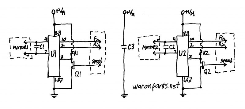
I designed this schematic for my driver board:

%mytable%|Symbol|Part/Value|Notes ||------|---------:|------||C1 |0.10 µF | ||C2 |0.10 µF | ||C3 |0.10 µF | ||R1 |1 kΩ | ||R2 |1 kΩ | ||Q1 |BS170 |NMOS ||Q2 |BS170 |NMOS ||U1 |BA6886N |driver||U2 |BA6886N |driver|
Part Selection Notes
- I really want to say I carefully picked these, but they were all mostly chosen because they were laying on my desk at the time.
- MOTOR1 and MOTOR2 are connected opposite from each other. The dot on the schematic is pin1: the red wire going to the motor. Because the motors are facing different directions, they need to be connected in a way that rotating in opposite directions moves the tank in one direction.
- Changing the direction of one motor connection is a lot easier than trying to remember that Fin and Rin are basically reversed on one of the drivers. I'd never remember which one. I'd rather let Fin be Fin and Rin be Rin.
- C1 and C2 reduce the noise that the motors generate and help to reduce current spikes.
- C3 reduces the noise that the board will generate on the power lines.
- Did you ever notice that capacitor values are always in farads, microfarads, and picofarads? Is saying "zero point one microfarads" easier than saying "a hundred nanofarads?"
- If you don't know how to read a capacitor's markings, a 0.10 µF capacitor is marked as "104".
- R1 and R2 are functioning as simple pull-up resistors for Vref on U1 and U2.
- Q1 and Q2 allow the microcontroller to toggle Vref on and off. Note that by using a transistor, pulling Speed high activates the transistor, pulling Vref low and stopping the motor. This means that Speed is active low, and could more accurately by labelled as Speed.
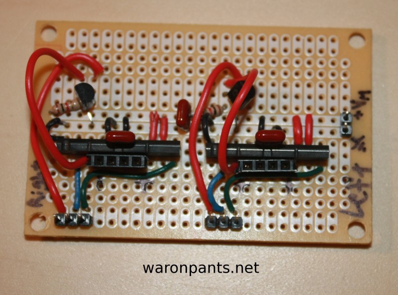
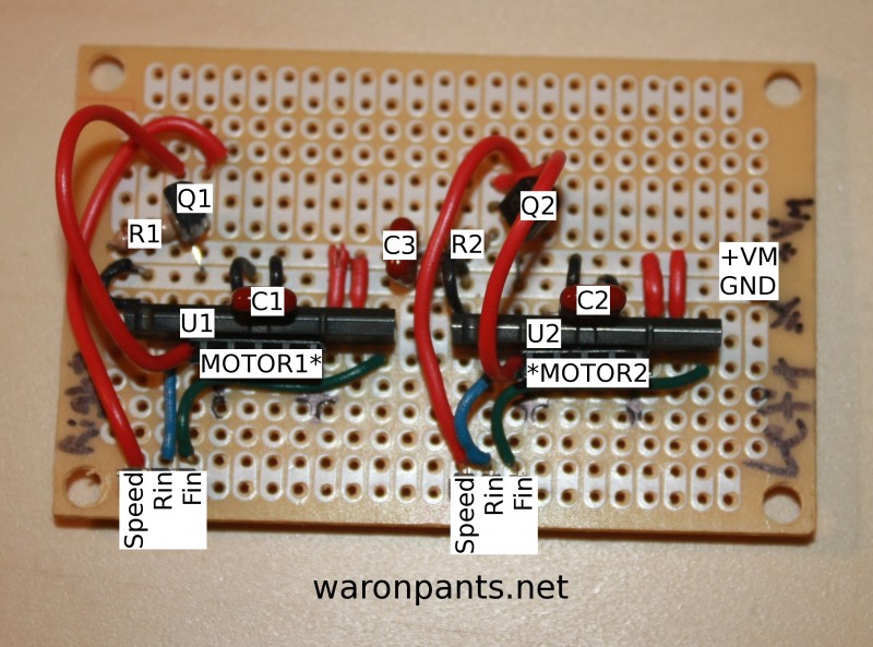
Here is a "map" of where everything is placed on the protoboard:

Finally, here is the total truth table for the entire board. I've lumped "brake" and "standby" into one item. They are considered the same thing pertaining to my project. I will only be using standby as the drivers use less power in this mode, but the motors themselves do not behave differently in either mode.
| Speed | Fin | Rin | Tread Direction |
|---|---|---|---|
| H | X | X | Stopped |
| L | L | L | |
| L | H | H | |
| L | H | L | Forward |
| L | L | H | Reverse |
