Canon Rebel XSi Remote Control
I finally put together another project post. It's a quasi-real project this time, too! It's not really a project because it took longer to type than to plan or build, but it should be helpful to someone out there!
Background
I tend to wander everywhere with my camera. I hate being caught without it. Sadly, my job prevents me from carrying it, so I miss a lot of photo opportunities when walking back and forth to work, but I digress.
I don't tend to want to be in most of my pictures, but sometimes it would be nice. The problems are that: I'm usually alone with my camera, or I'm usually with someone who doesn't know how to use my camera because it's a DSLR. I decided to build a remote control for it.
The remote control for my Canon Rebel XSi at the time of writing this article is $30 from Canon's website. I honestly didn't even think to buy a remote until I started writing this post. In true hacker spirit, I thought it would be fun to risk hundreds of dollars of camera equipment to build my own crappy knockoff.
Design
There was no way I was going to open my camera. I saw that there is a remote control port on the side, so I looked for a pinout description online. The port is a 2.5 mm (3/32 in) stereo jack that is also used for some older phone headsets. I didn't know how many contacts I would need. Luckily, it is a three contact jack. I can easily get two or three contact jacks from places like Radio Shack, but a four contact jack would have meant I would need to order it online. Because I already had every other part, I didn't want to have to pay shipping and handling for just a small jack.
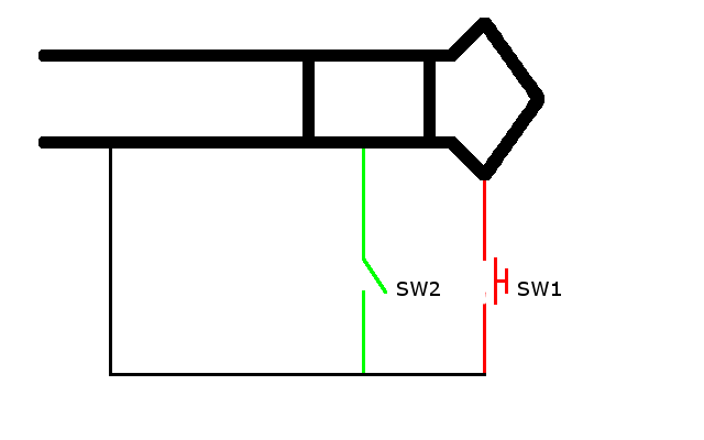
I found each contact's function from this website. I understand what the author was trying to accomplish, but I didn't really want to same setup. Here's a schematic of my design:

SW1 is an SPST momentary button switch. SW2 is an SPST button switch. I chose these colors to stay consistent with the website above. I also used the same colors for my actual wiring.
Closing SW2 shorts the ring to the base of the jack. This activates the auto focus and light meter. This is the same as pressing the shutter button half-way on the camera.
Closing SW1 shorts the tip to the base of the jack. This activates the shutter. This is the same as pressing the shutter button on the camera completely.
While testing, know that it's OK to short the tip to the ring. Nothing happens. Although, you should check with a multimeter before connecting this to your camera, anyway.
Parts List
This list of parts definitely isn't ideal. I chose these parts because they were conveniently at the top of my parts boxes. I know I have better parts, but it was late when I started to build this. I didn't care. I still don't. If this breaks, it's cheap enough to throw together another remote.
- Mint tin
- Nintendo power/reset switches from an NES (both buttons are one piece)
- Three lengths of stranded wire
- I needed flexibility. Solid wire would have been too stiff, and it would have cracked and failed over time.
- 2.5 mm jack
Assembly

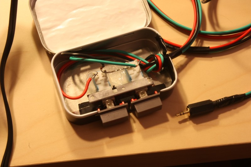
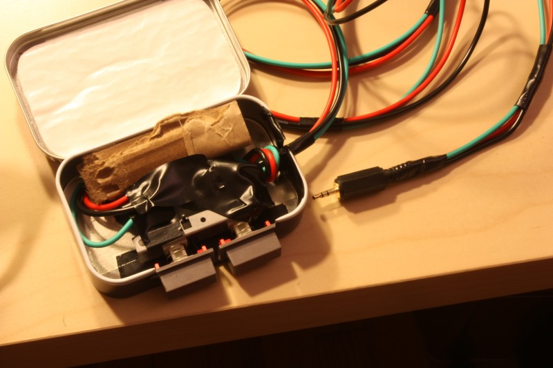
Since the assembly for this project is so simplistic, I didn't take pictures until I was done. I used tin snips to cut the sides of the mint tin. To make sure the edges weren't sharp enough to cut me or the wires, I wrapped the edges in electrical tape. I put a piece of two-sided tape on the bottom of the case just to hold everything in place while I put everything inside.
Once I was happy with the placement, I glued the switch assembly in place with craft glue, making sure not to get any glue near the moving parts of the switches. I put a loose overhand knot in the wires to act as a simple strain relief.

I let the glue dry. When I pushed a button, the whole assembly moved slightly. Even though it was springy and moved back when I let go, I figured that the buttons would slide inside over time. I rolled up a small piece of cardboard and stuffed it inside. Everything was fastened enough after that. I covered the exposed leads with electrical tape to insulated them. I left the paper that came with the tin in the top to act as another layer of insulation.
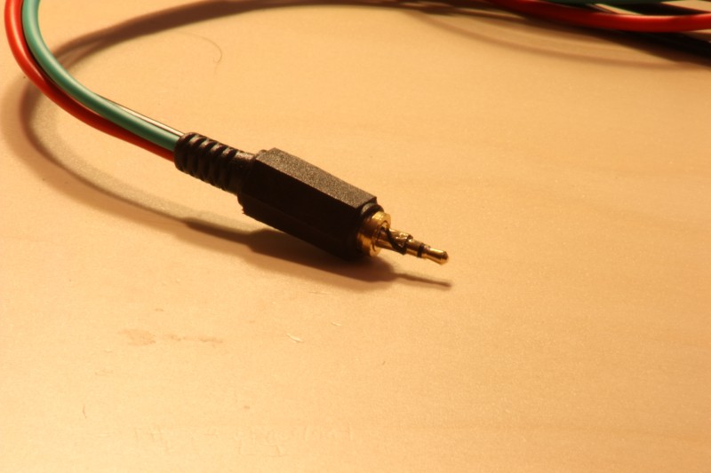
The 2.5 mm jack (already connected in the picture) was a bit tough. The gauge of wire I was using was too thick to fit through the sheathing, so I stretched it slightly using my pliers. However, when I tried to force the sheathing back on, I actually tore the foil off the jack. I'm glad I didn't order the jack online, because I would have had to order a second piece.

It worked the first time, but my multimeter detected an internal short circuit. After constantly sliding the sheathing on and off to solder and desolder the connector, it turned out that I accidentally had the button pushed in. I was a bit stupid.
Completion
After everything was put together and tested, I finally connected it to my camera at around 4AM, so I didn't set up the camera for an ideal picture. I would have taken a better one, but I had to leave for work about 4.5 hours after this picture was taken.

Lessons
- Normally when soldering I leave the leads long and trim them afterwards. When soldering to the jack, that wasn't an option. Starting with the leads extremely short and tinning them made this much easier.
- Flux is awesome. I melted the plastic insulation between the leads rather than heating the area where the solder was supposed to flow. Then, I remembered something I saw on the web: flux. I read that a little bit of flux helps tremendously. Normally, I would just add a little solder for its flux core, but there is very limited room inside of the jack sheathing. Also, I didn't want to risk having too much solder and short circuiting the leads, even though I used electrical tape anyway. I bought a small tin of flux a while ago, and I finally got to use it. I added a tiny bit of flux with a toothpick before soldering. I couldn't believe how amazingly easy this soldering job became with the tiniest bit of flux. I seriously can't stress how miraculous it is. I have to keep this in mind in the future.
